Technical Review
Introduction
In 2012, the UK Space Agency commissioned a technology feasibility study on behalf of Lunar Mission One. This was undertaken by a team of professional engineers managed by RAL-Space (https://www.stfc.ac.uk/RALSpace/default.aspx), at the Rutherford Appleton Laboratory in Harwell, UK. It superseded an original technology design concept created in late 2008.
The study addressed the following:
- Review and update the mission concept including launch, transfer, landing and in-situ operations.
- Review and update the space segment mass, power and telemetry budgets.
- Identify launch vehicle options and recommend a preferred approach.
- Document and render the updated baseline mission concept.
- Prepare an estimate of the cost of the entire space segment including margins and assumptions.
- Propose a credible schedule for the project design, development, launch and test.
- Identify critical technical issues for the space segment development, and recommend risk mitigation.
In addition, the team considered lunar sample return. It investigated the trade-off between a combined mission versus a separate follow-on mission. The risk-weighted cost benefit analysis concluded that a separate second mission would be preferable. This led to a further study and report later in 2012, though not included here.
Team Members
|
Name |
Affiliation |
Responsibility |
|
Olly Poyntz-Wright |
RAL-Space |
Team Leader |
|
Bob Parkinson |
Consultant |
Systems Engineer |
|
Adam Baker |
Kingston University |
Systems Engineer |
|
Phil Bustin |
WIPRO (formally with Logica) |
Drill |
|
Rob Gowen |
UCL MSSL |
Payload |
|
Dave Barnes |
Aberystwyth University |
Robotics |
|
Wayne Tubby |
RAL-Space |
Robotics & Configuration |
|
Christina McQuirk |
RAL-Space |
Mission & Propulsion |
|
Yang Gao |
University of Surrey |
GNCEDL |
|
Aron Kisdi |
RAL-Space |
Comms |
|
Simon Woodward |
RAL-Space |
Power |
|
Allan Dowell |
RAL-Space |
Thermal |
|
Cait Percy |
RAL-Space |
Structures & Payload |
|
Sev Gunes-Lasnet |
RAL-Space |
Cost, Risk & Schedule |
|
Arthur Smith |
Fluid Gravity |
Return Capsule |
|
Ben Couchman |
Fluid Gravity |
Return Capsule |
Method
Using a recently installed integrated software package for creating mission architectures, known as a Concurrent Design Facility (CDF), the team was tasked with working out how to take a payload of archive canisters, a suite of science instruments and a deep drill to the Moon’s South Pole. For lunar surface operations a robotic arm was added.
The value of the CDF was in using a linked model of the mission space segment to conduct multiple near-concurrent trade-offs between subsystems, mission parameters and technologies to ascertain the optimum design point for the mission given the agreed requirements. The proposed design was not therefore intended to be a comprehensive solution to the mission requirements itself, rather to stress test a proposed design, identify potential design weaknesses and highlight major technology risks. This design could serve as a baseline to compare and rank future industrial contractor proposals for best value.
The design philosophy aimed to derive the best value-for-money mission, i.e. to achieve a balance between cost, risk, and capability, and assumed a commercially managed mission development and operation.
The team designed the space segment to include the following components:
- A landing vehicle with a number of payload elements:
- a wireline telerobotic deep drilling system, of >10m class,
- a lunar (regolith) science instrument suite,
- capsules to be delivered to the borehole,
- a robotic arm to deploy the capsules, facilitate drilling, and interact with samples;
- A propulsion system which can achieve a soft landing;
- A navigation system for landing in a 100 by 100 meters target near the Lunar South Pole from a trans-lunar injection starting point;
- A communications system to transmit sufficient data back to Earth and to receive command instructions at the Moon;
- Suitable power generation, energy storage, thermal control and command data handling elements to perform mission functions for as long as possible;
- Survival of a lunar night was agreed to be desirable but not critical to the mission;
- A commercially procured launch vehicle or one provided under international collaboration.
Mission Sequence
The team developed the sequence of events for the Lunar Mission One mission concept as shown by the schematic below:
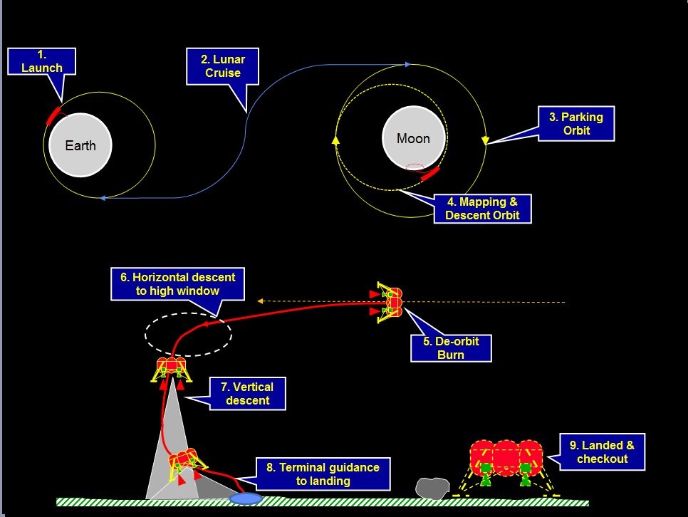
Lunar Mission One space segment mission concept |
Arriving at a practical lander design required a solution to a lunar descent and landing problem. This problem drives the entire lander design and can be addressed by breaking the sequence down into a number of steps, explained below.
- Earth departure and lunar cruise plus any mid-course corrections. These are well understood manoeuvres with low delta-V uncertainty and well defined start and end points, so do not greatly drive mission risk (Delta-V is the scalar measure of the impulse that is needed to perform a space maneuver, and is used to determine the mass of propellant required through the Tsiolkovsky rocket equation).
- Entry into a low 100km lunar ‘parking orbit’. This orbit should be stable and its parameters accurately measurable over at least a month.
- Adjustment of this orbit into a 100km ´ 10km ‘mapping & descent’ orbit, aiming to use the lander camera system to verify high resolution (<0.5m resolution) LRO (Lunar Reconnaissance Orbiter) data of the landing site. This orbit is not stable so a parking orbit must be returned to after imaging, to allow time for processing and planning descent to the lunar surface.
- Return to a parking orbit for processing and identification of the optimum landing site. This needs to be done a month in advance of landing so that lighting conditions are approximately the same for mapping and landing, within the limits of the optical navigation system.
- Return to the descent orbit, and initiation of a de-orbit or propulsion deceleration manoeuvre. This manoeuvre is designed to place the lander into a defined region of space above the lunar surface with velocity in a precisely calculated range. The lander thrust/weight ratio (T/W) is critical during this manoeuvre since it defines the trajectory velocity losses and the required system delta-V.
- This position and velocity ‘high window’ target can range between the extremes of a maximum velocity at minimum altitude (maximum T/W weight required, maximum translation) and minimum velocity at maximum altitude (minimum T/W, vertical descent). The lander reorients at this point to a vertical descent trajectory and maintains the continuous thrust begun at the start of de-orbit. Besides controlling vehicle attitude (allowing lateral movement of the vehicle), the RCS (reaction control system), uses small thrusters to provide attitude control of the descent rate, targeting a main engine cut-off at 10m altitude with zero vertical velocity.
- The target zone of 100m by 100m has been selected by mission planners on Earth and the lander will operate automatically to reach main engine cut-off. However the limitations of the camera mapping before landing mean that last minute hazard avoidance will be needed. This will operate autonomously with the option for teleoperator intervention from Earth to steer the lander away from apparent obstacles.
- Final landing will utilise a crushable landing gear structure to absorb the energy of the drop from main engine cut-off point and any residual vertical velocity. Residual lateral velocity will need to be minimised such that the final velocity vector remains inside the landing gear footprint, to minimise the risk of the lander overturning. A maximum landing site slope of 15° is recommended.
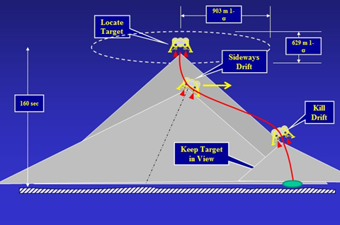
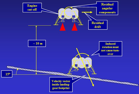
Terminal descent targeting and touchdown dynamics
Payload
The lander supports four principle elements:
Deep drill: The drill is designed to penetrate the lunar surface regolith (fragmented, unconsolidated rock) towards the underlying rock, at some 10-20m depth. The drill will then penetrate deep into the regolith, to a target depth of 100m. This will serve two purposes: firstly a deep borehole will allow storage of a large number of payload capsules, and secondly the depth will allow unprecedented scientific examination of the lunar subsurface. Apollo and Luna only sampled to within a few metres of the surface. The challenges associated with this deep drilling are summarised below with a schematic.
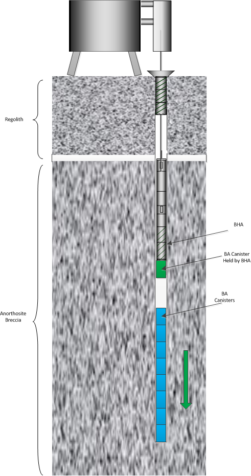
Drill Schematic showing lander...
- Post landing, determining a spot to drill vertically into the regolith, ensuring maximum borehole depth for the least effort.
- Dealing with the low bulk density of the lunar regolith which is believed to make initial drilling difficult (drill self-support, collapse of sides). Insertion of a ‘Spud’ or conical tube will be required to drill through the first ~0.5m of relatively soft upper regolith to allow the drill to maintain an accurate vertical path as it begins the borehole.
- Terrestrial boreholes are lined or cased to allow retrieval of the drill e.g. for bit replacement and waste removal. It has been assumed that once the borehole penetrates the lunar bedrock, the hardness of the anorthositic breccia will not require a liner. Some 600 round trips of the drill head are estimated to complete the borehole and deposit the payload capsules.
- Without a liner, borehole collapse above or below the drill is possible. Borehole collapse remains a risk even with a liner, and approaches to withdrawing a drill from below a collapsed region, and drilling back into a collapsed borehole from above have been considered.
- A robot arm serves to handle extracted cores from the borehole for analysis and disposal. Drill or robot arm failure is a risk which will need to be carefully managed
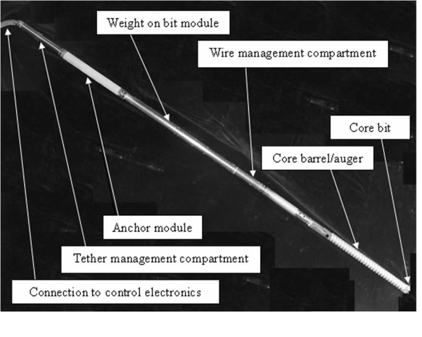
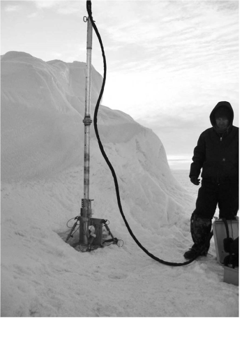
The team presumed the use of drilling technology originally prototyped in the US in the 2000’s, as shown below, but still needing up to $100m to develop to an operational version from its current status of TRL 5 (Technology Readiness Level – the standard method of estimating technology maturity, originally developed by NASA in the 1980s. A new technology normally needs to have reached TRL 5 before a mission is based on it.) (Drilling Systems for Extraterrestrial Subsurface Exploration, K. Zacny, Y. Bar-Cohen, M. Brennan, G. Briggs, G. Cooper, K. Davis, B. Dolgin, D. Glaser, B. Glass, S. Gorevan, J. Guerrero, C. McKay, G. Paulsen, S. Stanley, and C. Stoker. ASTROBIOLOGY, Volume 8, Number 3, 2008 © Mary Ann Liebert, Inc. DOI: 10.1089/ast.2007.0179.)
Unpublished design parameters had been provided to Lunar Mission One, including mass, power, dimensions and drilling performance, and these were incorporated into the lander parameters.
Robot arm: A multi segment, jointed robot arm is required to manipulate sample core segments, and is located nearby one of the four lander bays. The arm (1) delivers selected cores (each about 2.5cm diameter x 15cm long) to the science payload located in another lander bay, and (2) disposes of unwanted cores brought back up the borehole by the drill assembly. An arm design developed originally for small Mars lander missions has been proposed.
Science: an instrument suite has been proposed which will address a number of internationally recognised science goals for the lunar surface. In brief these include dating the South Pole Aitken basin, geochemistry and mineralogy, volatile examination, thermal profiling, radio astronomy and measuring the radiation, dust and charging environment. A set of instruments targeting these goals and not exceeding 30kg mass has been identified and will be located in a further lander bay, along with a sample handling mechanism. Currently baselined instruments include:
- Descent and landing site imaging cameras.
- Spectrometer suite (gamma ray, infrared, Raman and isotope) for determining chemical compositions and volatile analyses.
- Seismometers for extended measurement of moonquakes.
- Surface and deep permittivity probes to measure electrical conductivity and infer presence of lunar ice.
- Dipole aerials to investigate practicality of low frequency astronomy from lunar surface.
- Microscope based sample imagers.
- Temperature sensors to measure heat flow through the lunar mantle.
- Energetic particle or radiation detector to quantify environment.
- Dust analysis package.
Finally, a cassette or carousel mechanism designed to deliver payload capsules to the borehole for storage is required. Each capsule is assumed to be 4cm in diameter by 30cm long. Approximately 30 will be required, filling the borehole to a depth of around 10m. This capsule dispenser has not been studied during this exercise as its design is not considered a significant risk.
Lander Design
The team created a design with sufficient detail at subsystem level to provide a check on propulsion and mass budgets.
The key lander subsystems are:
- An octagonal structure braced by four internal shear panels attached to a central tube. Panels and thrust tube are made from high stiffness carbon fibre faceskins bonded to a Hexcel aluminium honeycomb core, with heritage from the Astrium UK ’Eurostar’ platform design.
- Propulsion uses a pressure fed storable propellant system, comprising four identical cylindrical tanks (two each containing MMH fuel and two MON oxidiser). Selection of this storable propellant combination and an appropriate mixture ratio reduces procurement costs and allows lander balancing. The main deorbit and descent engines are 400N class bipropellants (Leros-2B), which operate continuously from lunar deorbit until cut-off just above the lunar surface. Lander thrust/weight ratio and attitude is modulated by smaller bipropellant thrusters delivering 22N thrust each. Propellant pressurisation tanks containing Helium gas are included in the design but are not shown. Propellant tanks are structurally mounted to the panels and thrust tube using CFRP (Carbon Fiber Reinforced Plastic) struts with Titanium alloy end caps.
- The landing system comprises four fixed (non-deployable) tubular aluminium legs which contain a crushable honeycomb filler that is designed to absorb the energy of impact. This design approach, used on the Apollo lunar modules, aims to create a balance between descent system complexity and absorption of a range of possible landing loads.
- The avionics is primarily built around the guidance navigation and control (GNC) system, with its on board data handling. The GNC system will utilise commercial off-the-shelf elements as far as possible. A star tracker and sun sensors are required for in-space navigation, while an inertial measurement unit (IMU) and radar altimeter monitor the descent. The most challenging element is the vision based navigation system, described earlier. A radiation tolerant computer such as SSTL’s OBC695 runs on-board data handling and is complemented by a dedicated signal processor unit for the navigation system.
- The communications system comprises a single high gain 0.5m diameter parabolic antenna and a multiple low gain antennae, plus a dual redundant S-band (2.24GHz) transceiver. The parabolic antenna uses a single axis motor drive which can ‘see’ the Earth in its beam pattern for up to 120° of lander rotations and up to 15° of lander tilt from the local horizontal. Ground stations in the UK and Hawaii could provide near 24 hour coverage during the mission, or a global network could be used such as NASA’s DSN (Deep Space Network) or ESA’s ESTRACK (European Space Tracking network).
- Power is provided by GaAs advanced triple junction solar cells covering the upper portion of the outer surface of the lander octagon (see image). A peak power requirement of 625W including margins can be met on the lunar surface. During lunar transfer and descent the power requirement is ~1/3 of this. A Li-ion or Li-polymer battery with a 40Ah capacity is included for eclipse period energy storage during lunar transfer and orbit. This may assist with thermal control during night time hibernation after the primary surface mission concludes.
- Thermal control utilises both passive (multilayer insulation) and active (electrical heater) elements to ensure a balance between internal power dissipation, solar irradiance, lunar absorption e.g. IR and radiated losses to space. Challenges will be to maintain sufficient lander temperature during a lunar night for an extended missions, and making allowances for in-space thermal balance, although neither of these are considered to pose major risks.
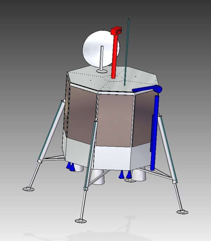 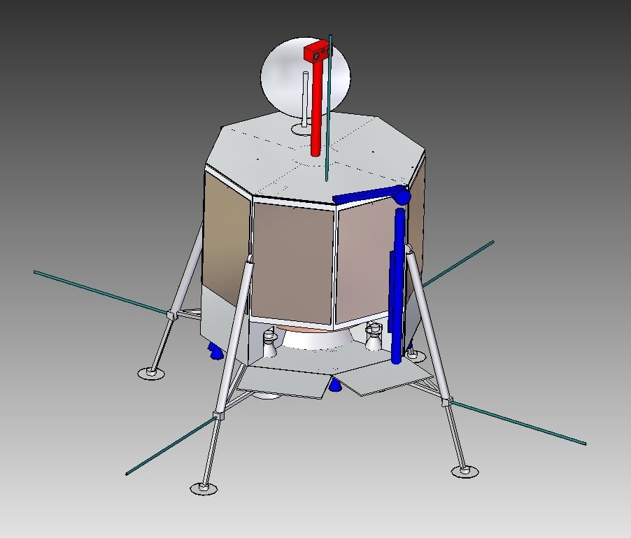 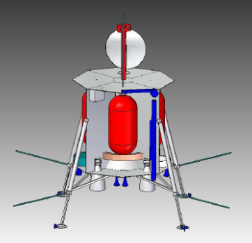 |
| Lander in flight, as landed, and exploded view showing propulsion tanks and surface camera (red), and drill housing plus deployment arm (blue). |
Key Risks
During the analysis, the team concluded these would be the top level technology risks:
- Drill design & operations.
- Guidance, navigation & control for descent & landing.
- Landing gear energy absorption.
Mass Budget
The estimated mission mass breakdown, on the surface with fuel spent, is provided in this table.
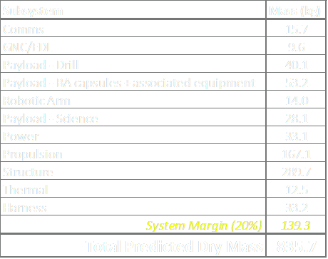
Significant mass ‘milestones’ for the mission are (in metric tons):
- 13.45t LEO delivery mass (capacity of baseline launcher).
- 2.69t system wet mass for fully fuelled lander injected into lunar transfer orbit.
- 0.836t lander mass delivered to lunar surface, empty of propellant, including 20% system margin on subsystems.
- 0.135t payload delivered to lunar surface and supported by lander.
The mass budget is dominated by the structure, the propulsion system including propellant tanks and the payload elements.
Launcher
The Lunar Mission One mission analysis assumed an injection from low Earth orbit (LEO) to lunar transfer using the launcher upper stage. The lander propulsion system was sized for delta-V requirements from the transfer mid-course correction to landing. Disposal of the upper stage post mission was considered.
A launch vehicle capable of delivering the lander onto a lunar transfer trajectory is therefore required with the following characteristics:
- Sufficient payload mass to a low Earth orbit so that an upper stage can deliver the fully fuelled lander onto an Earth escape trajectory or Moon intersecting highly elliptical Earth orbit.
- Heritage to reduce mission risk.
- A fairing able to accommodate the stowed lander diameter and height.
- Supplied from a contractor located in a nation such as the United States with availability either commercially or by international agreement.
At the time of the study, the team derived this short-list:
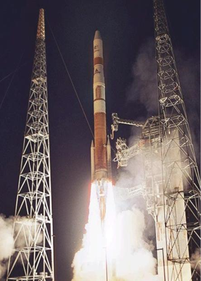
- Delta IV M+ (5, 4).
- Falcon-9 Block 2 (superseded by 1.1 from 2012).
- Atlas V 521/522.
- Falcon-9 heavy (TBC).
A number of non-US launchers including Ariane V ME, Proton or Angara would also be applicable. For lowest risk, the Delta IV was selected for the analysis.
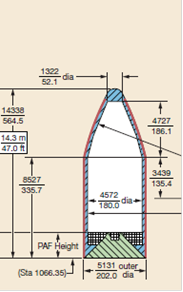 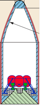  |
| Schematic of payload fairing envelope for Delta IV M+; lander accommodated inside its fairing (note lack of height constraint); launch from Cape Canaveral. |
Costs
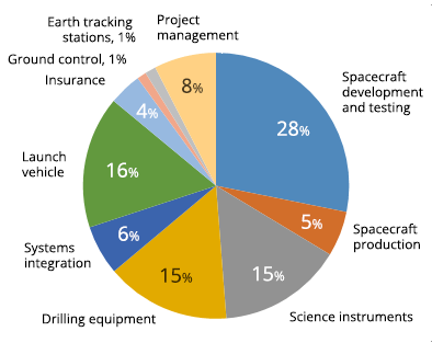
The mission cost prediction is itemised below.
|
Spacecraft development and testing |
$212m |
|
Spacecraft production |
$41m |
|
Science instruments |
$114m |
|
Drilling & canisters |
$114m |
|
Systems integration |
$45m |
|
Launch vehicle |
$121m |
|
Insurance |
$30m |
|
Ground control |
$9m |
|
Earth tracking stations |
$10m |
|
Project management |
$57m |
|
Total |
$751m |
Schedule
The initial estimate to develop the space segment and complete its primary mission from the start of commercial funding was 8.5 years. The revised schedule indicated that the mission could be completed in less time, as little as 7 years. The development and/or procurement risks if not retired may extend phases C and D1 (design, subsystem build and test) by up to 2 years in total. A conservative estimate would be 9 years from commercial funding to completion of the commercial mission. A nominal schedule is shown below. Note the overlap between early mission phases.
[NB All dates from a start in January 2013.]
|
Phase |
Activity |
Total Period (months) |
Nominal END date |
|
A/B |
Systems design & preliminary technology risk reduction. Competitive design studies by contractors. Completed at PDR. |
30 |
Mid 2015 |
|
C |
Detailed subsystems design, further technology risk reduction. Completed at CDR. |
24 |
Mid 2016 |
|
D |
D1: Subsystem (module) manufacturing and testing. Completed at MRR. D2: Spacecraft assembly, integration, test (AIV) & delivery; Launch assembly & preparation. Completed at FRR. |
36 |
Early-Mid 2019 |
|
E |
Launch & Space Operations. Transport from Earth to Moon |
1 |
Mid 2019 |
|
F |
Primary mission Lunar Operations : Drilling, science & archiving |
~6-9 |
End 2019 |
|
|
|
TOTAL: ~8 yrs |
|
Conclusion
The team concluded:
“The mission appears to be feasible with only modest deviations from the original pre-feasibility design concept. The baseline launcher, mass margin and desired payload elements are complementary and collectively allow a credible sequence of mission phases. A number of risks relating to descent guidance navigation & control, drill and robot arm robustness & redundancy, and landing structure have been identified and risk mitigation strategies have been identified. The precise launcher performance and price need to be confirmed. It appears reasonable that the primary mission can be carried out within a lunar day depending on the precise landing site. A detailed Phase A/B study by one or more contractors will aim to confirm the conclusions made here and refine the key budgets including cost and schedule.”